Tel: 0086-577- 62600386 62602786
Fax: 0086-577-62600796
Skype:+8613736310909
E-mail:xk@cnxiya.com
WhatsAPP:+8613736310909
Website: http://www.cnxikai.com
Download sample:

SKYPE:+8613736310909
Wechat:+8613736310909
WhatsAPP:+8613736310909
Viber:+8613736310909
E-mail:xk@cnxiya.com
QQ:195457709
wechat:xiyapower
Dingtalk:+8613736310909
Tags :
一、Product overview and features
Bypass comprehensive action technology is a new operation technology to improve the power supply reliability of distribution network. It includes distribution network routine operation, live line operation, bypass operation, mobile power operation and other operation modes. Yce-lbs-12kv / 24kV engineering bypass load switch is the core equipment to meet the new comprehensive bypass operation technology. The switch adopts flexible power cable, self-locking quick plug cable connector, bypass switch, mobile box transformer vehicle and other equipment to build different distribution units in the form of building block combination for bypass power supply to users. It can not only enable the power distribution operators to complete the line maintenance work under the state of uninterrupted power supply, but also provide temporary power supply for the fault repair of difficult cable lines, reduce the scope of power failure, reduce the impact of power failure on users, and improve the reliability of power supply. The bypass load switch adopts SF6 gas with outstanding insulation and arc extinguishing performance and advanced main circuit structure. The switch characteristics are as follows:
1.1. High purity (99.9%) SF6 gas with outstanding insulation and arc extinguishing performance is injected into the body, so the arc breaking time is short (1 / 2cycle), the insulation recovery speed is fast, and the insulation performance is good.
1.2. The very short arcing time during load current breaking consumes little contact at the breaking position, so there is no need to maintain or replace the main circuit.
1.3. The main circuit operating mechanism is a simple inverted triangle structure, so it is not affected by high-frequency vibration, gravity and external impact caused by earthquake or strong wind. It has very stable performance and long mechanical life.
1.4 the body is made of SUS304 stainless steel treated by painting, so it will not be corroded. The operating mechanism and mechanical transmission part are also installed inside the sealing body, so there will be no misoperation due to corrosion.
1.5 at atmospheric pressure (0 kg · f / C ㎡), it can also * * ensure its insulation performance and breaking performance. That is, even if the SF6 gas inside the body leaks and its pressure drops to 0, it can ensure all insulation performance and breaking performance.
1.6 with live display and counting display;
1.7 nuclear phase function
二、Electrical performance parameters
2.1 product standards
IEC60502
GB3804
GB/T12706. four
GB/T8905
GB11023
DL/T844
2.2 service environment
① Service temperature: - 40 ~ + 85 ℃
② Humidity condition: 0 ~ * * * (relative humidity)
③ Service height: below 1000m above sea level
2.3 rated parameters
Kind | Unit | Rated | ||||
model | - | |||||
Rated voltage | kV | 12 | 24 | |||
Rated current | A | 400 / 200 | ||||
Rated frequency | Hz | 50/60 | ||||
Insulation performance | Rated impulse withstand voltage | Relatively | kV | 75 | 125 | |
Between in-phase terminals | kV | 95 | 145 | |||
Rated power frequency withstand voltage | Relatively | kV | 42 | 64 | ||
Between in-phase terminals | kV | 48 | 79 | |||
electric current Opening and closing capacity | Load current | A | 400 / 200 | |||
Exciting current | A | 21 | ||||
Cable charging current | A | 25 | ||||
Line charging current | A | 1.5 | ||||
Rated short-time withstand current | KA/4s | 20 | ||||
Rated closing current | kA | 50 | ||||
gas pressure | Rated pressure | ㎏·f/㎠ | 0.5±0.1 | |||
Explosion proof pressure | ㎏·f/㎠ | 4~6 | ||||
Manual closing / opening power | ㎏ | 18±2 | ||||
Weight | noumenon | ㎏ | 50 | |||
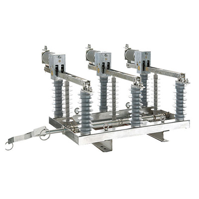
三、Introduction to components of bypass load switch


Item | Product Name | Item | Product Name |
1 | Counter | 8 | Lifting handle and lifting lug |
2 | Operating handle and nameplate | 9 | Right armored sleeve socket and dust cover |
3 | Left armored sleeve socket and dust cover | 10 | Nuclear phase analyzer / controller |
4 | Manual locking device | 11 | Bypass switch holder |
5 | SF6 barometer | 12 | Grounding hole |
6 | SF6 gas injection valve | 13 | High pressure explosion-proof device |
7 | Lower tripod |
Outline drawing of bypass load switch


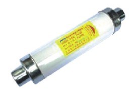
①套管(Bushing)
The bushing adopts epoxy resin with outstanding insulation performance and suitable for outdoor. The gap between the sleeve and the body is sealed with a sealing ring (O-ring) with good sealing performance. The conductive rod is made of T2 copper rod。

[Incoming and outgoing line bushing]
②防爆法兰(SafetyMembrane)
The safety device is set to prevent the shell from bursting and the contents from flying away when the gas pressure inside the switch body rises sharply due to abnormalities inside the switch body. The explosion-proof pressure of explosion-proof flange is 4 ~ 6 kg · f / C ㎡. The position is in the opposite direction of the operator, so as to protect the operator.

③气体注入口(GasFillingPort)
Please do not open the cover of the gas injection port under normal use, otherwise the gas inside the body may leak. Even if the internal gas pressure drops, it can be refilled through this injection inlet.
④手动合闸/分闸手柄(ManualHandleforClose/Open)
This handle is used to operate the switch manually.
⑤手动闭锁装置(ManualLockingDevice)
When the switch body is locked mechanically, the device can be used for locking operation in the closing or opening state.
⑥吊钩(LiftingLugs)
Use this hook when lifting or installing the switch. Do not use other parts during lifting or installation, otherwise the product will be damaged.
⑦本体支撑架(Leg)
When placed on the ground, the support is arranged so as not to damage the lower part of the switch body.
⑧接地端子(GroundTerminal)
It is the terminal connecting the switch body and the grounding wire. 22 ~ 38mm2 grounding wire can be directly connected to the terminal without other accessories.
⑨动作计数器(Counter)
Indicates the number of actions of the ontology
⑩压力表(PressureGauge)
It is used to display whether the gas pressure inside the body is normal or not. The diameter of the pressure gauge is 76mm, and the normal and abnormal ranges of internal gas pressure are distinguished by different colors.
-Normal pressure range (green):0.1~0.5㎏·f/C㎡
-Abnormal pressure range (red):0.1㎏·f/C㎡below

四、Operation of switch body
4.1 protection grade
The protection grade of switch body and mechanism box is IP67.
4.2 insulation and arc extinguishing
The insulation and arc extinguishing medium adopts high-purity (more than 99.9%) SF6 gas with good insulation and arc extinguishing performance, with * short arc extinguishing time (1 / 2 cycle) and good insulation recovery characteristics.
The principle of compressed air arc extinguishing is used. When the load current is disconnected, due to the electrical characteristics of SF6 gas, when the arc is cooled in SF6 gas until a relatively low temperature, it is still conductive. The arc is disconnected when the current crosses zero, and the current cut-off before the current crosses zero is small, thus avoiding high operating overvoltage.
4.3 operation of body
① Manual closing / opening operation
Please confirm the current closing / opening state of the switch before manually operating the body. Facing the manual operating handle, in the opening state, the front indicator points to the opening (right), and the red closing ring is on the upper right side. At this time, if you want to close, just pull down the closing ring on the upper right side. At this time, the front indicator points to the closing (left), and the green opening ring is on the upper left side.
The lower part of the switch body is also provided with a closing / opening status indicator, which is mechanically connected to the main shaft inside the switch, so the current status of the switch can be accurately understood.
The force required for manual operation of the switch is 18 ± 2 kg. The manual operating mechanism is spring mechanism.
② Manual locking / unlocking operation
If it needs to be locked electrically and mechanically in the closing or opening state, just pull down the manual locking pull ring. To unlock, just push the locking tab upward. Opening / closing operation cannot be carried out under manual locking state.

4.4 operation instructions of nuclear phase controller
● correctly connect the switch and controller through cables and connect the switch and line.
● turn on the power switch of nuclear phase controller. Press the lamp test key, all indicator lights should be on, and the buzzer sounds, indicating that the battery voltage meets the requirements, and the indicator light and buzzer are normal. Otherwise, the indicator light or buzzer shall be replaced to keep the phase corer in a normal usable state.
● three red lights in * * line are nuclear phase error indication. The phase indicator corresponding to phase error is on and the buzzer sounds at the same time.
● a green light on the second line is the correct indication of nuclear phase. The green light indicates that the phase is correct.
● the third line is the power indication on the power side, and the light is not on when it is 20% lower than the rated voltage. When the light is on, it indicates that the corresponding phase is energized. The fourth line is the power indication on the load side, and the light is not on when it is 20% lower than the rated voltage. When the light is on, it indicates that the corresponding phase is energized.
● when the six green indicators on the power side and load side are on, and all three red indicators of nuclear phase error are not on, the green indicator of correct nuclear phase is on, and the buzzer does not ring, it can be closed.
● the nuclear phasor will use 9V laminated battery as power supply. When the battery voltage is lower than 7V, the low battery red indicator in the lower right corner will be on, and the buzzer will sound to prompt the replacement of the battery. The normal nuclear phase can be realized only after the battery is replaced.
● when any nuclear phase error indicator is on, it is a nuclear phase error and switching on is not allowed. Closing is allowed only when 6 power on indicators and correct nuclear phase indicators are on and the phase error indicators are not on. Simply put, if the red light is not on, 7 green lights are on, and switching on is allowed.
五、Nuclear phasor panel

六、Installation and storage of switch body
6.1 product storage method
If you are not in a hurry to install the product and need to keep it for a period of time, please refer to the following points:
-*Do not unpack and keep the original state when leaving the factory.
-Try to avoid places with high ambient temperature or direct light.
-Try to avoid places with very high humidity or ponding on the ground.
6.2 installation of switch body
6.2. 1 install the holder on the electric pole;

6.2.2Hang the bypass switch on the holder;


6.2.3Bypass switch mounting hardware
Install the retainer
七、Solutions in case of problems
7.1When there is a problem with the switch body
In case of problems on the switch body during installation or use, please check and solve them according to the following methods
No. item cause analysis result solution
1、The gas pressure drops below the normal pressure range (*) After re inflation, maintain normal pressure for a period of time. The gas leaks naturally. After re inflation, the pressure drops again. The switch body has problems that cannot be solved on site. The internal pressure of the withdrawal switch increases, resulting in explosion-proof flange burst (* *) that cannot be solved on site. Withdraw the switch
2、The manual locking device cannot be operated with the manual closing / opening operating handle. The manual locking device is locked and released. The manual locking device is not in the locked position. The operating force is insufficient to increase the force. There is a problem in re operating the operating mechanism. The problem cannot be solved on site
Serial number | project | Cause analysis method | Analysis results | resolvent |
1 | The gas pressure drops below the normal pressure range (*) | After re inflation, maintain normal pressure for a period of time | Natural gas leakage | Re inflate |
After re inflation, the pressure drops again | There is a problem with the switch body | If the problem cannot be solved on site, withdraw the switch | ||
The explosion-proof flange burst (* *) due to the increase of internal pressure | If the problem cannot be solved on site, withdraw the switch | |||
2 | It cannot be operated by manual closing / opening handle | The manual locking device is locked | Manual locking | Release manual locking device |
The manual locking device is not in the locked position | Insufficient operating force | Increase strength and operate again | ||
There is a problem with the operating mechanism | The problem cannot be solved on site |
(*) gas pressure changes with ambient temperature, so please refer to "SF6 gas pressure temperature characteristic curve".
(* *) in case of explosion-proof flange burst, please refer to "measures in case of explosion-proof flange burst".
7.2 measures in case of explosion-proof flange burst
① The bursting of the explosion-proof flange indicates that the device inside the switch has been damaged, so be careful when checking or withdrawing.
② The explosion-proof flange burst switch cannot maintain normal insulation and opening and closing performance. Therefore, please withdraw and replace the product in time.
③ This kind of switch (the explosion-proof flange has burst) decomposes a large amount of toxic gas during arc of internal SF6 insulating gas, so be careful when withdrawing.
④ When the explosion-proof flange bursts, the toxic gas leaked from the inside of the body will pollute the switch surface. Therefore, relevant personnel must wear protective gloves and work clothes when checking or withdrawing, so that the pollutants cannot contact the skin.


7.3In case of problems that cannot be solved on site
If the problem cannot be solved according to the above methods or cannot be solved on site, please contact the company.